
Green Energy and Sustainability ISSN 2771-1641
Green Energy and Sustainability 2021;1(2):0007 | https://doi.org/10.47248/HKOD902101020007
Original Research Open Access
Analytical model for the simulation of Trombe wall operation with heat storage
Catherine Baxevanou
†
 ,
Dimitrios Fidaros
†
,
Aris Tsangrassoulis
†
,
Dimitrios Fidaros
†
,
Aris Tsangrassoulis
†
Correspondence: Catherine Baxevanou
Academic Editor(s): Thomas Kotsopoulos, Georgios Martinopoulos, Giorgos Panaras
Received: Sep 27, 2021 | Accepted: Nov 10, 2021 | Published: Dec 17, 2021
This article belongs to the Special Issue Selected Papers from the 12th National Conference of IHT
© 2021 by the author(s). This is an Open Access article distributed under the terms of the Creative Commons License Attribution 4.0 International (CC BY 4.0), which permits unrestricted use, distribution, and reproduction in any medium or format, provided the original work is correctly credited.
Cite this article: Baxevanou C, Fidaros D, Tsangrassoulis A. Analytical model for the simulation of Trombe wall operation with heat storage. Green Energy Sustain 2021; 1(2):0007. https://doi.org/10.47248/HKOD902101020007
Passive solar systems, such as the Trombe wall, are cost-effective ways to reduce the energy consumption of buildings for heating, cooling, and ventilation. The operation of these systems can be simulated either with Building Energy Simulation Tools—BES like TRNSYS, EnergyPlus, etc either with Computational Fluid Dynamics—CFD. In both cases, the purchase of special software and/or special programming skills are required. In parallel analytical calculating tools are being developed, which also require some programming to solve an implicit system of non-linear equations but with fewer software requirements. The majority of analytical models concerns energy balance models for steady-state conditions with the result that heat storage is not taken into account, which in the case of a Trombe wall has a significant effect on the developed transport phenomena.
In the present work, an analytical energy balance implicit model was developed for the simulation of the transient operation of a Trombe wall taking into account the heat storage. Using this model, the operation of a Trombe wall for 7 typical days of the year was simulated. The results are presented in terms of the daily evolution of the temperature with which the air enters the room served by the passive system, of the temperature of the Trombe wall surface adjacent to the served room, and of the airflow rate inside the air gap. These results are compared with the results that a system without heat storage would give. Both systems are assessed based on annual performance as calculated by a quasi-steady explicit model. The developed model can be used to calculate the operation of a Trombe wall as well as to supply explicit quasi-steady models with values for airflow rate inside the air gap for Trombe wall operation without mechanical ventilation. Feeding these values to a quasi-steady model developed by authors it was found that the increase of storage wall heat capacity, either changing the storage wall material, either using phase change materials, can offer better utilization of Trombe wall heat gains up to 35% yearly.
Background: The present work aims to develop an analytical model for simulating the operation of a Trombe wall in a transient state taking into account the heat storage in the wall.
Methods: A closed system of equations is developed, based on 5 energy balances and a series of assumptions and auxiliary relations, to calculate the operation of a wall Trombe with heat storage with an hourly time step.
Results: Characteristics Trombe wall temperatures and mass flow rate through the air gap are calculated for typical days of 7 winter months. These are used for the calculation of utilizable heat gains from Trombe wall.
Conclusions: The model that does not take into account heat storage predicts higher temperatures and air mass flow rate in the gap than the present model by 10%. However heat storage increase the utilizable heat gains by 35% compared with a system without heat storage.
KeywordsTrombe wall, heat storage, energy balance model, analytical model, implicit model
Passive solar systems, such as the Trombe wall, are cost-effective ways to reduce the consumption of buildings for heating, cooling, and ventilation [1]. The operation of these systems can be simulated either with building energy simulation software (BES models) [2,3] or with Computational Fluid Dynamics (CFD) [4,5]. BES models provide a 1D analysis with at least sub-hourly year-round results and coupling with the entire building heat flows, while CDFs provide at least a 2D model, but they are limited in terms of simultaneously implementing all other building heat flows and performing a year-round, simulation. BES models usually make simplified assumptions about the nature of flow, especially in the air gap, while CFD offers a more accurate calculation of flow and consequently heat transfer in the critical areas. Nevertheless, both approaches require the purchase of specialized software and/or advanced programming skills. Other models that can be more easily used by Engineers are the quasi-steady models [6,7] which, however, only concern operation with mechanical ventilation. In these quasi-steady models, the dynamic effects of passive solar systems are taken into account indirectly with the use of gain utilization factors. On the other hand, quasi-steady models can take into account the characteristics of the space they serve [8]. Finally, analytical models are developed, which also require some programming to solve the system of equations they come up with but with fewer software requirements. However, the majority of these analytical models concern steady-state approaches, with the result that heat storage is not taken into account, which in the case of the Trombe wall has a significant effect on the development of transport phenomena.
The solar walls, also known as Trombe-Michel walls, are part of the building shell and are designed to absorb solar radiation and store heat which they later deliver to the building thus reducing its energy needs. Properly designed and installed, a solar wall can reduce energy needs by up to 30% [9].
Researchers’ efforts to develop analytical energy balance models to describe the operation of passive solar systems have a long history. In [10] an analytical model was developed to calculate the energy efficiency of a Trombe wall with a monthly step based on an equivalent electrothermal circuit making a series of simplistic assumptions. Based on this approach, of the equivalent circuit, several analytical models were developed. Most of them concern the operation of a solar chimney [11,12] thus ignoring the heat storage while other models refer to the Trombe wall [13], but again, in its version without thermal mass and describe steady-state conditions. Thus, the dynamic phenomena related to heat storage are not modeled correctly. However, some analytical models that take into account the heat storage for solar air heaters could be used in the development of similar models for the Trombe wall [14].
All of these models are implicit and require an iterative process to solve the proposed system of equations. But unlike the quasi-steady models, the system of equations used is closed and no assumptions are needed to calculate the air supply to the gap, even if no mechanical ventilation is used, since the flow is calculated in detail.
The present work aims to develop an unsteady analytical model for simulating the operation of a Trombe wall in a transient state taking into account the heat storage in the wall to model the dynamic phenomena. This model is validated against measurements available in the literature and it is used to calculate the operation of a Trombe wall for 7 typical days of the year and the results are compared with those of a model that does not take into account heat storage [13]. The results are presented in the form of a daily variation of air outlet temperature from the air gap, the temperature of the wall surface in contact with the room being served, and the air mass flow rate through the air gap between the cover and the absorbing wall. The results of the two models supply explicit quasi-steady models with information about the air mass flow rate through the gap to evaluate the operation of Trombe walls without mechanical ventilation with and without heat storage. Finally, a parametric study for the investigation of storage wall heat capacity is presented.
The basic geometry, the principle of operation, and nomenclature adopted are given in Figure 1.

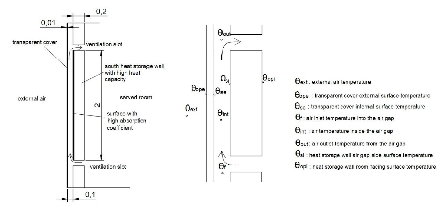
Figure 1 Basic geometry and temperature nomenclature on the Trombe wall.
The energy balance model for describing the Trombe wall function taking into account the hourly heat storage was compiled by modifying the model developed by the authors [13] according to the work [14].
The basic equations of the model are three energy balance equations [11,15] which correspond to the heat transfer from the inner surface of the cover to the air in the gap of the Trombe wall, the heat transfer by the air inside the air gap, and the heat transfer from the air in the gap to the inner surface (surface in contact with the gap) of the storage wall.
The first energy balance equation concerns the air inside the air gapWhere,
Where, θope [K] is the transparent cover external surface temperature, Re* [m2K/W] is the transparent cover thermal residence, Ni* [-] is the diffusive radiation coefficient, aest [-] is the transparent cover absorptivity, It [W/m2] is the total solar radiation incident in the transparent cover external surface, Rcv1 [m2K/W] is the convective resistance between the transparent cover internal surface and the air inside the air gap, and Rrd [m2K/W] is the radiative resistance between the two air gap surfaces.
The third energy balance equation concerns the inner surface of the heat storage wall (which is in contact with the air gap). The heat storage of the Trombe wall will also be taken into account in this equation.Where, S [W/m2], is the solar radiation absorbed by the Trombe wall selective surface, Rcv2 [m2/WK] is the convective resistance between the air in the air gap and the inner surface of the storage wall (surface facing the air gap), θopi [K] is the heat storage wall temperature on the room facing surface, Ri* [m2/WK] is the thermal resistance of the heat storage wall, ΜW [kg/m2] is the heat storage wall mass reduced to the wall surface, Cp,w [J/kgK] is the specific heat capacity of the heat storage wall, and Tw [K] is the average heat storage wall temperature.
Where, Cd [-] is the discharge coefficient taken equal to 0.6, ρ [kg/m3] is the air density, Acs [m2] is the cross-section area of the air gap, Ar [-] is the inlet/outlet fraction, g [m/s2] is the gravity acceleration, and L [m] is the distance between lower and upper ventilation slots.
The convective heat exchange coefficient between the transparent cover internal surface and the air inside the air gap is given by the relationshipWhere, σ=5.67x10⁻⁸ [J/s] is the Stefan-Boltzmann constant, εg [-] is the transparent cover inner surface emissivity and εw [-] is the heat storage wall inner surface emissivity.
To close the system of equations two more energy balance equations are used. One concerns the energy balance between the surface of the heat storage wall that is in contact with the served room and the air inside the room.In this way, a closed system of equations is created.
Where, w [m/s] the wind velocity.
The solar radiation, S [W/m2] absorbed by the inner heat storage wall surface (with high absorption coefficient) is calculated from the following relationship for vertical wall with south orientationWhere, τn [-] is the transparent cover transmittance at normal incident radiation, αn [-] is the heat storage wall inner surface absorptance and ρd [-] is the transparent cover inner surface reflectance.
The thermal resistances of glass and wall are calculated according to the EN-ISO-6946.
Finally, the heat storage wall mass, Mw [kg/m2] reduced to the Trombe wall area is calculated byThe model was applied to the Trombe wall described in the paper [17] with the name NVTW2/NSD to calculate the temperature profile in cross-section of the wall at 14.00 on October 31, beginning the calculations from 9.00. For this day the paper [17] gives data about the radiation and the developed temperatures. Figure 2 gives the profile of the temperature across the wall as calculated with the present model. Specifically, the temperature values are given in the middle of the air gap, on the surface of the heat storage wall that is in contact with the gap and on the surface of the heat storage wall that is in contact with the room. From Figure 2 it comes out that the calculated temperatures are compared very well with the measured temperatures given by [17].
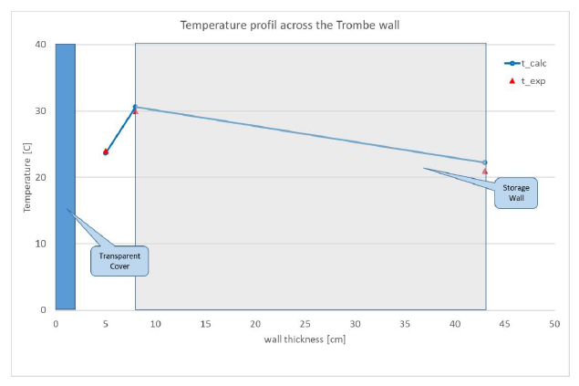
Figure 2 Temperature profile across Trombe wall at 14.00.
The operation of a Trombe-Michel wall, installed in an experimental lodge such as that shown in Figure 1, was examined for 7 typical days of the year (15th day of October, November, December, January, February, March, and April) considering that the Trombe wall serves a room located in a geographical position with a latitude of 39.39° and a longitude of 22.75°. The hourly climatic data was produced by the monthly climatic data given by TOTEE20701-3 [18] using the clear sky model for radiation [19] and the sinusoidal approach for temperature [20]. The cover is considered to be a double 4-15-5 low-e glass and the collection surface of the heat storage wall is painted black. The room design temperature is 20 μC. The material properties of the modeled experimental facility are given in the following table 1. It is assumed that the Trombe wall operates only during the day hours with the slots remaining closed during the night and for the periods in which the wall cannot contribute to the thermal needs covering.
Table 1 Material properties.

Figure 3 shows the daily variation (a) of air outlet temperature from the air gap, θout, and (b) of the heat storage wall room facing surface temperature, θopi, for Trombe wall calculations with storage mass and Trombe wall without storage mass as well as the daily variation of external air temperature, θext, for the examined site for October. In the same figure in a secondary axis is presented the total solar radiation incident in the transparent cover external surface, It [W/m2].
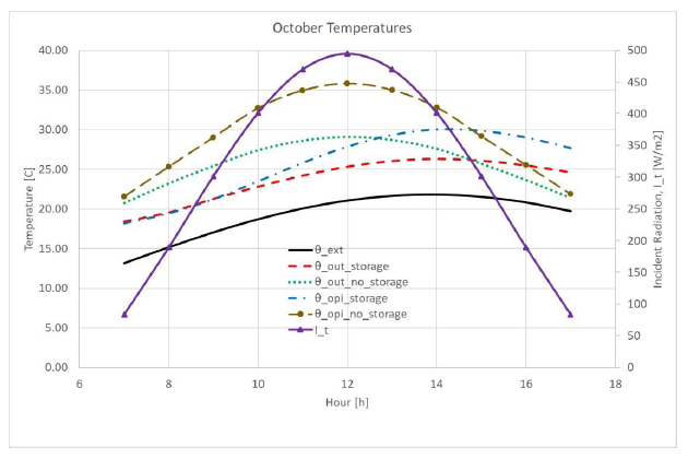
Figure 3 Daily variation of Trombe wall temperature and incident radiation, October.
Specifically: (a) the external air temperature, θext, is given by a black continuous line, (b) the air outlet temperature from the air gap for a system with heat storage, θout,storage, is given by a red dashed line, (c) the air outlet temperature from the air gap for a system without heat storage, θout,nostorage, is given with a green line with dots, (d) the heat storage wall room facing surface temperature for the system with heat storage, θopi,storage, is given with a blue line with dashes and dots and finally (e) the heat storage wall room facing surface temperature for a system without heat storage, θopi,nostorage, given with brown line with dashes and solid circles of the same color, (f) the incident to transparent cover radiation is given with a continuous purple line with purple triangles.
The first observation is that the temperatures of the system without heat storage are higher than those of the system with heat storage until the early afternoon hours and mainly follow the change of the incident solar radiation. On the contrary, the temperatures of the heat storage system show a time lag in the incident radiation of 2 hours, while in the first 2 hours the temperatures are lower than the room design temperature (20 °C), since the heat from the incident solar radiation is used to increase the wall temperature. Therefore, during these hours, it is preferable to keep the ventilation slots closed. However, at the end of the day, both the surface temperature of the wall and the air leaving the gap temperatures are higher and the wall continues to provide heat to the room during discharge even when there is no external incident radiation.
Figures 4, 5, and 6 show the same daily temperature variations for December, February, and April using the same symbols. During the rest of the summer months, the Trombe wall can either function as a solar chimney and the model developed can be modified according to the temperature of the air entering the gap, or it can be completely covered/shaded so as not to burden the serviced room with additional solar heating gains.
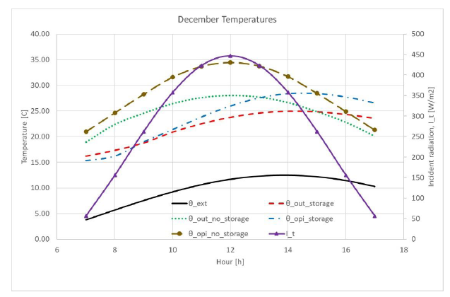
Figure 4 Daily variation of Trombe wall temperature and incident radiation, December.
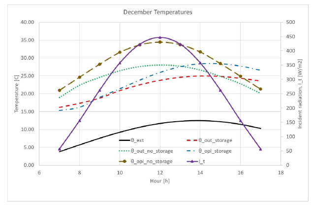
Figure 5 Daily variation of Trombe wall temperature and incident radiation, February.
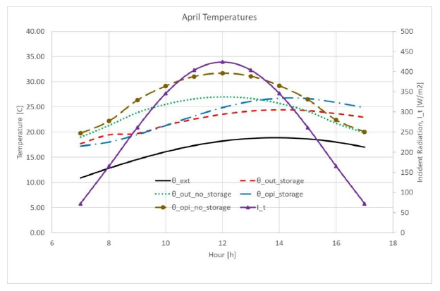
Figure 6 Daily variation of Trombe wall temperature and incident radiation, April.
During the examined winter months, the Trombe wall for heat storage systems begins to contribute to room heating after the first three hours of the morning. During December, and February the time lag is 3 hours. In April, the efficiency of the Trombe wall decreases due to the reduction of the available solar radiation in the southern vertical wall and the reduction of the corresponding transmittance-absorptance product that depends on the angle of incidence despite the higher external temperature. December and February show almost the same behavior while the best performance corresponds to October because October is characterized by a combination of relatively high temperatures and high levels of solar radiation in the vertical South wall.
Figure 7 shows the daily variation of air mass flow rate through the air gap for the months under consideration for a heat storage system. For each month the air mass flow is given only for the hours during which the Trombe wall contributes positively to heat demand cover, assuming that during the other hours the ventilation slots are closed.
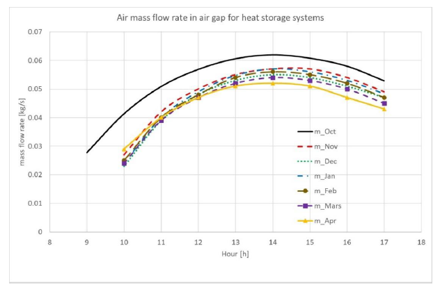
Figure 7 Air mass flow rate in the air gap for systems with heat storage.
The maximum air mass flow rate is achieved for October and the lowest for April. The rest of the winter months do not differ significantly. The air mass flow depends on the available radiation on the south wall and the angle of incidence that determines the transmittance-absorptance product as well as on the difference between indoor and external air temperature. It starts from values greater than 0.02 kg/s while the maximums are over 0.05 kg/s and is maintained above 0.04 kg/s at the end of the solar day. Also, the peaks appear with a time lag which are more intense in the winter months.
Figure 8 shows the daily variation of air mass flow rate for the months considered for a system without heat storage.
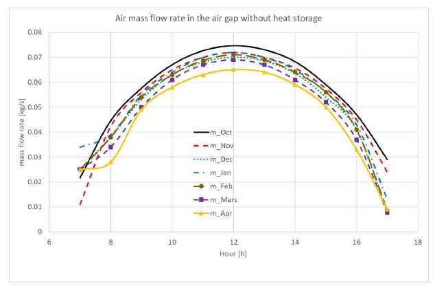
Figure 8 Air mass flow rate in the air gap for systems without heat storage.
The maximum values of the air mass flow rate, which follow the incident solar radiation, are higher than those achieved by the system with heat storage due to larger temperature differences. Here, too, the largest air mass flow corresponds to October and the smallest to April, but without impressive differences.
Finally, Figure 9 shows the annual variation of the average daily air mass flow in the air gap for systems with and without heat storage. The air mass flow rate for a system with heat storage is given by a continuous black line while the air mass flow for a system without heat storage is given by a dashed red line.
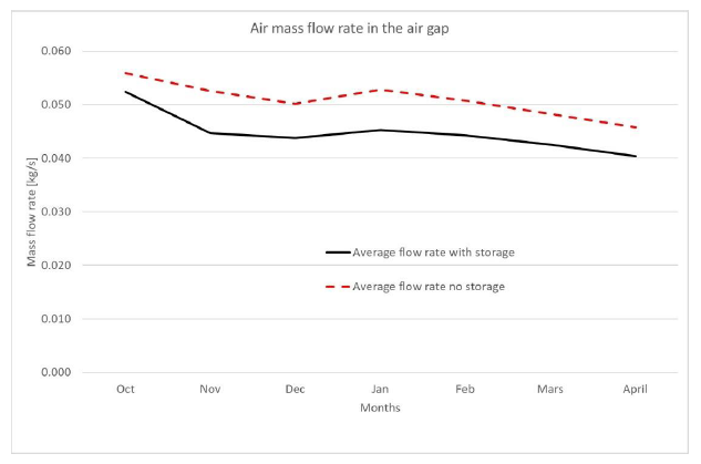
Figure 9 Yearly variation of average air mass flow rate in the air gap.
The trend is the same in both cases with a maximum in October and a minimum in April. The air mass flow rate of the heat storage system is on average 10% lower than that of the heat storage system. However, if these mean values are used to estimate thermal solar revenues through the Trombe wall with a quasi-steady model [8] this difference leads to a reduction in revenues of less than 1%.
However, since these revenues cannot always be fully utilized, the comparison of systems should be based on not the ideal thermal gains (assuming that all thermal gains can be utilized, so the gain utilization factor will be (1) but on the utilizable heat gains from the Trombe wall. Using the same quasi-steady model results that the final utilizable heat gains of the system with heat storage are 35% (annual average) higher than those of the system without heat storage. This difference starts from 15% in October and reaches 45% during the winter months.
The influence of the storage wall’s specific heat capacity was investigated with a short parametric study. Two different materials were investigated for the construction of the storage wall keeping all the characteristics (geometry and properties) as presented in Table 1. Specifically, the use of ceramic material, with Cp,w = 800 [J/kgK], and of shoulder bricks, with Cp,w = 1500 [J/kgK], were investigated for the characteristic day of October. Feeding the quasi-steady model, described above [8], with the air mass flows for the two different materials the monthly ideal and utilizable heat gains are calculated. In Table 2 the percentage change of air mass flow through the air gap with regard to the case study for the two examined materials is given, as well as the corresponding changes of monthly ideal and utilizable heat gains are presented.
Table 2 Parametric study for various storage wall heat capacities.
The use of bricks, with a 20% lower heat capacity, increases the mass air flow by 6% while it decreases the ideal heat gains by 5% and the utilizable heat gains by 7% for October. On the contrary, the use of shoulder bricks with a 50% higher heat capacity decreases the mass airflow by 4% but increases the ideal heat gains by 10% and the utilizable heat gains by 15%. The observed trends are in line with the results of the comparison between the extreme cases of not accounting for the mass heat storage and of using PCM, presented in the previous paragraph.
In the present work, an energy balance model with hourly time step was developed to calculate the performance of a Trombe-Michel wall taking into account the heat storage in the Trombe wall. This model was used to calculate a Trombe wall operation and the results were compared with those of a corresponding model that does not take into account heat storage. The temperatures developed in the Trombe wall with both models and the air mass flow through the air gap were examined. The proposed energy balance model succeeds in modeling the modification due to heat storage and the time lag in the provided heating due to the utilization of thermal mass. Based on the results, the Trombe wall in question at this location has the most effective operation in October and the worst in April. During the rest of the winter months, the yield remains almost the same.
The model that does not take into account heat storage predicts higher temperatures and air mass flow rate in the gap than the present model by 10%. However, when the calculated mass flows are used in a quasi-steady model, this difference is reduced to less than 1% in that the heating gains from the ideal operation of the Trombe wall (in which all heating gains are utilized). While, if in the quasi-steady model, the utilizable heat gains are calculated taking into account the thermal mass of the system, it results that the system with heat storage is superior by 35% of the system without heat storage.
According to the parametric study, the increase of the storage wall heat capacity increases both the ideal and the utilizable heat gains since it shifts the appearance of maximum temperatures to afternoon hours extending the discharge period to hours without sunshine.
Not applicable.
Not applicable.
Not applicable.
General Secretariat for Research and Innovation—GSRI (Former General Secretary for Research and Technology—GSRT) of Greece and Hellenic Foundation for Research and Innovation (HFRI).
The authors have declared that no competing interests exist.
Catherine Baxevanou: Conceptualization, Methodology, Software, Writing-Original Draft, Data Curation, Visualization
Dimitrios Fidaros: Conceptualization, Methodology, Software, Writing-Review & Editing, Project administration, Funding acquisition
Aris Tsangrassoulis: Conceptualization, Writing-Review & Editing, Supervision.
The work has been carried out under Research Program HFRI: Numerical and experimental assessment of solar air heater systems performance towards zero energy buildings-NUMEXSAH, funded by GRSI (former GSRT) and HFRI.
| 1. | Agrawal B, Tiwari GN. Building Integrated photovoltaic thermal systems: for sustainable developments. Chapter 4. Solar Heating and Cooling Concepts for Buildings. Cambridge, UK: Royal Society of Chemistry; 2010. [Google Scholar] [CrossRef] |
| 2. | DesignBuilder Software Ltd. cited 11 Apr 2018. Available from: https://designbuilder.co.uk. |
| 3. | EnergyPlus. cited 20 Jun 2020. Available from: https://energyplus.net. |
| 4. | Gan G. A parametric study of Trombe walls for passive cooling of buildings. Energy Build. 1998;27(1):37-43. [Google Scholar] [CrossRef] |
| 5. | Hami K, Draoui B, Hami O. The thermal performances of a solar wall. Energy. 2012;39(1):11-16. [Google Scholar] [CrossRef] |
| 6. | I.O.f. Standardization. ISO 13790:2008 Energy performance of buildings — Calculation of energy use for space heating and cooling. Switzerland: ISO; 2008. |
| 7. | Ruis-Pardo A, Alvarez Dominguez SA, Fernadez JAS. Revision of the Trombe wall calculation method proposed by UNE EN-ISO 13790. Energy Build. 2010;42(6):763-773. [Google Scholar] [CrossRef] |
| 8. | Baxevanou C, Fidaros D, Tsangrassoulis A. Analytic model for solar air heaters performance assessment. Proceedings of the RoomVent 2020; 14-17 February 2021; Torino, Italy.. |
| 9. | Wang R, Zhai X. Handbook of energy systems in green buildings. Berlin, Heidelberg, Germany: Springer; 2018. |
| 10. | Duffin RJ, Knowless G. A simple design method for a Trombe wall. Sol Energy. 1985;34(1):69-72. [Google Scholar] [CrossRef] |
| 11. | Balocco C. A simple model to study ventilated facades energy performance. Energy Build. 2002;34:469-475. [Google Scholar] [CrossRef] |
| 12. | Ong KS. A mathematical model of a solar chimney. Renew. Energy. 2003;28(7):1047-1060. [Google Scholar] [CrossRef] |
| 13. | Baxevanou C, Fidaros D, Katsoulas N, Mekeridis E, Varlamis C, Zachariadis. Simulation of radiation and crop activity in a greenhouse covered with semitransparent organic photovoltaics. Appl. Sci. 2020;10(7):2550. [Google Scholar] [CrossRef] |
| 14. | Saxena A, Varun El-Sebaii AA. A thermodynamic review of solar air heaters. Renew. Sust. Energ. Rev. 2015;43:863-890. [Google Scholar] [CrossRef] |
| 15. | Bloem JJ, Lodi C, Cipriano J, Chemisana D. An outdoor test reference environment for double skin applications of building integrated photovoltaic systems. Energ. Buildings. 2012;50:63-73. [Google Scholar] [CrossRef] |
| 16. | I.O.f. Standardization. ISO 6946:2017 Building components and building elements. Thermal resistance and thermal transmittance. Calculation methods. Switzerland: ISO; 2017. [Google Scholar] [CrossRef] |
| 17. | Briga Sá A, Cunha JB, Lanzinha JC, Paiva A. An experimental analysis of the Trombe wall temperature fluctuations for high range climate conditions: Influence of ventilation openings and shading devices. Energy Build. 2017;138:546-558. [Google Scholar] [CrossRef] |
| 18. | Technical Chamber of Greece. Technical Guidance of Technical Chamber of Greece TOTEE 20701-3-2010 - Climatic Data. Technical Chamber of Greece Athens Greece. Greek. 2010. [Google Scholar] |
| 19. | Duffie JA, Beckman WA. Solar engineering of thermal processes. New Jersey: Wiley; 2013. [CrossRef] |
| 20. | Parton WJ, Logan JA. A model for diurnal variation in soil and air temperature. Agric. Meteorol. 1981;23:205-216. [Google Scholar] [CrossRef] |

![]()
Copyright © 2026 Pivot Science Publications Corp. - unless otherwise stated | Terms and Conditions | Privacy Policy


